
This condition is referred to as magnetic saturation. Further increases in the magnetic bias field give rise to larger net magnetic dipole moments until a point of saturation, beyond which further increases in the bias field produce no change. Application of a DC magnetic bias field causes additional dipoles to align, and the magnetic moment increases. In ferrite materials, some of the magnetic dipole moments can be aligned. In non-magnetic materials, the dipoles are randomly aligned, and there is no net magnetic dipole moment. The reverse traveling wave is rotated into the input cone resistive layer and absorbed, i.e., converted to heat energy.Īll materials have electron spin states which create magnetic dipoles. The direction of rotation is the same for both the forward and reverse waves, giving rise to the non-reciprocal nature of the device. No currents are generated in either resistive layer by the forward traveling wave, and there is no associated loss. The field is rotated 45 degrees counterclockwise as it passes through the ferrite and emerges normal to the resistive layer in the output cone. The E-field in the TE10 mode is normal to the resistive layer in the input waveguide.
#RF ISOLATOR FERRITE CORE FULL#
Micro Harmonics is currently the only worldwide producer of full band, low loss isolators in the WR4.3 (170 to 260 GHz) and WR3.4 (220 to 330 GHz) bands, and is developing designs for the WR2.8 (265 to 400 GHz) and WR2.2 (330 to 500 GHz) bands.įigure 2 Spinning electron angular momentum and spin magnetic dipole moment vectors. These numbers are game changers, and mmWave system developers are reconsidering their use. These isolators have a typical insertion loss of less than 1 dB in the WR10 band and about 2 dB in the WR3.4 band. developed a line of mmWave isolators designed for low insertion loss. In 2015, with funding from NASA JPL, Micro Harmonics Corp. Yet, for many years following that work, very little changed in the commercial market. In 2001, Erickson 1 demonstrated that insertion loss can be dramatically reduced. At these frequencies, the constituent parts are very small, difficult to fabricate and align - and with more than 7 dB insertion loss, there is not much demand. There are few suppliers in the bands above 110 GHz isolators for the WR4.3 and WR3.4 bands, produced many years ago, are now difficult to find.

At mmWave frequencies, the insertion loss becomes problematic: in the WR10 band (75 to 110 GHz), insertion loss can exceed 3 dB in the WR3.4 band (220 to 330 GHz), the loss can be greater than 7 dB, making the isolators impractical. Insertion loss is low in the microwave bands, steadily increasing with frequency. While there are more than a dozen vendors worldwide, the design has largely remained static since the 1970s. Traditional Faraday rotation isolators provide greater than 20 dB of isolation over full waveguide bands, with some exceeding 30 dB.

They can be mitigated by inserting isolators between the multipliers, resulting in a much smoother frequency response and improved bandwidth. Standing waves cause dips - even nulls - in the output of the multiplier chain. They are primarily used to suppress standing waves that arise due to impedance mismatches between highly-tuned components, such as those found in frequency multiplier chains.

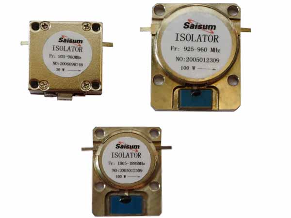
Isolators are non-reciprocal devices, passing electromagnetic (EM) signals in one direction and absorbing them in the reverse direction.


 0 kommentar(er)
